TimberSurf’s Model Railway
Modelling Tips, Links & Guides for Model Railways
Lumsdonia Railway

A web page for my indulgence and sharing ideas and irregular updates on my Model railway


SALE
PLUS
A guide to the programmable logic ready made Arduino PCB
Programmable Electronics Guide
Arduino
Prologue
I am no stranger to industrial PLC’s, so it is no stretch for me to know that if I want to automate actions on the layout, then a programmable platform is needed. The things I want to do are beyond that which a bespoke electronic circuit is capable of, so the obvious choice might be a PICAXE (programmable Integrated Chip), but an Arduino is a better option due to being more powerful and just as cheap! The basic chip on a pcb ready to go, is less than £2 !!!
WHAT IS AN ARDUINO?
“Arduino is an open-source electronics platform based on easy-to-use software (your kidding?) And hardware. It's intended for anyone making interactive projects.”
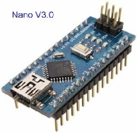
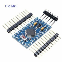
There are several variants, but I will use the smaller Pro Mini (only has serial connection) or Nano (has USB connector). Each has 20 connections for inputs or outputs (I/O). They are capable of driving RC servo’s directly. They come “empty” and after downloading the free software [IDE] from the Arduino site, you have to write the programme in C++, or find a source to crib from and upload to the chip.
I am by no means an expert, but have picked it up quite quickly (others without my background may not)

Future projects/programs
Building crane crate up/down
Crane loading through 90 deg
Kiddies swing
Pram push
welding arc
Kiddies merry go round
Helicopter
Grass mower
Windmill
House chimney smoke
Building on fire
Door opening
JCB
Level crossing gates
Police car *
Fire engine **
Pedestrian crossing traffic lights
Projects/programs written so far
Belisha Beacons
Traffic lights
Level crossing barrier with lights
Garage car lift
I will slowly write up each project and add them to this page as I develop them. Bookmark this page and keep checking back
OK, let me kick it off with a simple hypothetical layout, lets call it 'Theadonia'.
Although most jump in and think Arduino is capable of sitting on and interfacing with DCC, it is not the only path! There are those that are just DC and Arduino can compliment that scenario as well. (and obviously it has its uses for non track devices as well)
So for the first example, lets investigate block indication.
Initially we will ignore its use for train control and signalling, we will just concentrate on indication. (mimic panel)
If we say had 50 blocks, that would mean running 50 wires back to the mimic! (spaghetti junction). Ditto if there were 50 points, that would mean 50 or 100 wires back from the mimic to all the points!
The arduino is capable of compressing this wide number into a few wires and passing the information (status) very fast in a serial mode (one at a time, sequentially incrementing the next chunk and so on) in a short period of time (a few milliseconds).
Let's say Theadonia has 12 blocks, detected by 2 arduino's that need to be displayed as led's on the mimic.
In each Block Arduino, the status of all points is known from 6 inputs and is stored as binary as 000000 (all unoccupied).
We can compress this data into hexadecimal and send over a 2 wire communication bus.
So our six bits of information must be read as a 8 bit string (byte) for conversion to Hex.
Thus, all unoccupied (000000) = decimal 0 = 00 in hex
{Binary starts from the right}
So, first block occupied ([00]000001) = decimal 1 = 01 in hex
fifth block occupied ([00]010000) = decimal 16 = 10 in hex
sixth block occupied ([00]100000) = decimal 32 = 20 in hex
second and fourth block occupied ([00]001010) = decimal 10 = 0A in hex
So the first Block Arduino can transmit one hex chunk of data to the Mimic Arduino as hex
The second Block Arduino can transmit one hex chunk of it's data to the Mimic Arduino as hex
Each one has a different address
We can then get the Mimic Arduino to filter the addresses and poll for information from each Block Arduino in turn.
Thus it will see the status of the first Block Arduino as a hex value, then the status of the second Block Arduino as a hex value and store both values in a table.
The Mimic Arduino can then read the the table, convert the hex back to binary and allocate each individual bit (block status) to individual outputs that are in turn connected to specific individual LED's on the mimic front.
So in a similar manner to DCC, multiple Arduino's can be used on a two wire network to transmit and receive lots of data, in the form of addressable parcels of information.
There are many protocols to choose from as to how Arduino's talk to each other. I2C, SPI, UART, RS232, RS485, serial, Bluetooth, RF, CANbus, WiFi, etc. Some are only good for a few feet, other will go miles! (or thousands of miles via the internet) (yes you can run trains at home while your at work!)
Distributing data via coms to multiple Arduinos
TERMS
Molex/Molex header (0.1 pitch)
There are hundreds of connector types in industry, but some are more common than others. One loose standard is to use a pitch of 1/10th of an inch between holes in a PCB, also sometimes referred to as 2.54mm pitch. Many types of veroboard and stripboard are arranged to this dimension. To allow easy connection, multi pin connectors are made to suit this pitch. One early manufacturer called Molex, created a range of connectors that could be soldered to boards, the proprietary name has stuck! (Like calling a vacuum, a Hoover). Dupont is another manufacturer name they are referred as.
They come in a rage of 1 to 40 in a row and sometimes in two or three rows. Crimped connectors are used to connect wires to connectors, the fixed part is usually has pins to allow soldering (and is usually called a Header). Some two row connectors can be had with IDC [Insulation Displacement Connection]. Several types are available with “key” registration (a pip on one side) to ensure connection the right way round, but most for Arduino have no key.
3 wire servo connectors adhere to this standard.
Arduino types
Depending on with Arduino board variant you get, it will either come with Molex headers or may come with just plain holes, ready for something to be soldered in, sometimes the board is supplied with the Molex headers loose, so you can choose what or how you attach them.
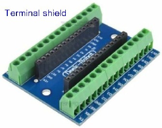
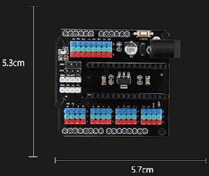
Shield
A Shield is a secondary PCB [Printed Circuit Board] that the Arduino either sits on or is connected too. It is essentially an interface between the generic Arduno PCB and other items. The most basic is just a PCB that has screw terminals that allows wires to be attached without using Molex connectors or by soldering
Sketch
The Arduino is essentially a CPU [Central Processing Unit] chip that has multiple connections with power drivers to allow direct connection to the world via TTL [Transistor Transistor Logic), 5V DC]. On it’s own, it does nothing. It needs a set of instructions that tells it what to do when it see’s inputs and which outputs to drive under certain conditions. This instruction set defines the conditions and outcome. Most commonly, this is called the software program. As long as the program is written in a way the CPU understands, it can be permanently stored in the CPU and the system will act on the stored program each time it is powered up. In the Arduino world, the program is referred to and called a ‘SKETCH’.
There is a series of “Fun with Arduino” by RudyB
on his website rudysarduinoprojects and Rudysmodelrailway accompanying YouTube videos, that takes you through the basics and on to some useful applications