TimberSurf’s Model Railway
Modelling Tips, Links & Guides for Model Railways
Lumsdonia Railway

A web page for my indulgence and sharing ideas and irregular updates on my Model railway


SALE
PLUS
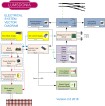
Train control will be with three NCE Pro boosters, each with a separate bus to three districts, District 1 (Green line) will be to the Phase one board, District 2 (Red Line) will be to the phase 2 main boards and District 3 (Violet Line) will be to the lower storage board. It will be run at the top of the 4” frame at the back of the boards. Generic detection/brake/signalling PCB’s will be mounted on the face of the frame just below, this enables the festoon lamps to be seen by looking under the board.
The bus will be a twisted pair of 2.5mm (multistrand) singles in brown and blue, containment (wire fasteners) will be screwed on “P” clips. At each join between main boards the pair will have a short length of heatshrink (to hold the twist together) and terminate in blue spade crimps. (This gives several points to split the bus for fault finding and ease of disconnection, if I ever move house).
At several points along each main board the wires will dip in and out of pairs of yellow female spade crimp. A red male spade crimp will be mated to supply droppers. Each dropper will immediately go to a generic detection/brake/signalling PCB and then on to the track. All dropper cables will be multistrand single 0.75mm blue and brown wires. For the few parts that do not have block control, the PCB will be replaced by just a festoon lamp.
A detailed description of the planned controls
Lumsdonia Electrics Design
I intend to use DCC Concepts “Cobalt” stall motors, these have two changeover contacts and need a “reversing” voltage. I originally intended to use SEEP solenoid motors, but as I need 2 contacts, one for electro frogs and the other for direction indication and they only have one, I would need a relay for every point, Cobalts have enough switches and are slow motion. I will use 6 core “alarm” cable for single points and a 8 core to pairs of points with a 6 core between them. This gives me a pair (red & Black) to drive the point motor, a pair (Blue & Yellow) for point direction with (green) a third for the common supply. If two points are required to work in tandem then another pair (orange and brown) will indicate the direction of the second point, wired via the first point. This keeps the wiring simple, so a multicore will run “point to point” from each point motor to each mimic.
I will use two 9VDC wall plug-in adapters as the power supply (9-0-9) for point motors and a 10A 12VDC switch mode PSU for the LED’s in the mimic (suitably fused)
Each point wire will be terminated in a 5 (or 7) way DIN male connector and appropriate chassis socket on the mimic panel.
DCC Bus wiring
Point Motor Wiring
There will be 2 x 32 Lighting circuits, actioned via an Auto-Off-Manual switch, driven in auto from a PC based program through a “LED-WiZ” USB output circuit. See Tip201 This will be built in to the “Action” control panel, With a LED on the front to show status. There will be a 37 way ribbon cable from each 32 way switch panel to a bus splitter board wich will divide 8 circuits on a 10 way IDC cable along the length of the main board, at various points an IDC connector will be fitted and required channel picked off from a 0.1in female 10 pin connector on a sub distribution board via 0.1in pins to servo motor leads (2 circuits per lead). These will run to resisters and the LED building and street lamps.
Lighting Wiring
There will be 16 “Auxiliary” circuits for things like moving cranes, moving figures, building smoke, welding arc circuit, etc, etc. Circuits, actioned via an Auto-Off-Manual switch, driven in auto from a PC based program through a “Denkovi” USB relay circuit. This will be built in to the “Action” control panel, With a LED on the front to show status. There will be a 37 way ribbon cable running the length of the main board, at various points an IDC connector will be fitted and required channel picked off from a 0.1in male 34 pin connector using crimped Molex connectors. These will run to circuits in the panel and on to devices or direct. (16 further wires available for future use)
Action Wiring
Each District will have a Digital volt and Amp meter built into a small display panel to be mounted at eye level above the Boosters
Controls will consist of 4 control panels. One small “power” panel will be mounted above the boosters to display control condition. One will be a small “Action” panel, with switch banks to control everything but the track. There will be two “Mimic” panels that will Graphically represent the track junctions and have point switches, point direction indicators, block occupancy indicators. One for phase 1 mounted below the middle board and the other mounted above the main board. Panels will be de-mountable and all internal wiring soldered and fed to sockets at the rear.
Control System
Design

When I first saw Peco had introduced a servo controller for point control, I got excited! .......until saw the price! (£12.50 ea point)
I recently discovered the possibility of using Arduino (cheap) nano boards that can be programmed to be a controller (£2.50 drives 4 points), but this means some programming (learning curve), soldering and an interface circuit. Although this may still be the cheapest option prorata, the answer in my case is to use this Megapoints at £60 per 12 (£5ea) its not a bad price and is way easier than developing your own (works out of the box)
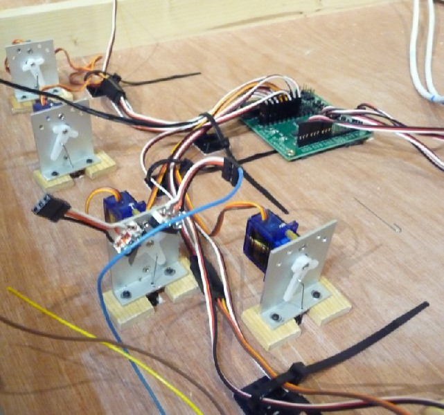
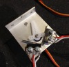
I have now developed a mechanism to hold the servo and give local switching. The first attempt included some 10x35 wooden batten with a hole routed in it to accommodate the servo, two micro switches mounted on the top of the wood and piece of wood at right angles to mount with. The fulcrum point for the 1mm piano wire was an issue, too sloppy and will wear over time. I decided to make the head of the tee with aluminium and screw to the wood, but realised it would just be simpler to make the whole thing from metal. A lot of research later and I have found some right angle aluminium bar that is just the right size, some "off the shelf" brass spacers to offset the servo from the face and the design is done! Servo, two micro switches, piano wire, 2 types of screws and the aluminium will total £1.89 per point!
So £5 for Megapoint and £1.89 for parts (+20p for servo harness) = About £7.09 per point!
New Point Motor Servo Wiring


A common return and signals is wired between the mimic panel and the Megapoints board
Phase A is complete and wired up to a mimic (switch) panel
LED’s will be added later
Note 4 different switch styles, to give tactile position
The great advantage of a printed paper sandwich is I can easily go back and change the graphics/add Logo/background picture/etc
The track will be divided into 4 meter sections (blocks) and isolated every 2 meters. Both 2 meter sections will be fed by a block sensor circuit for train detection. If the block is occupied, that signal will be fed to the previous block and activate the DCC asymmetric braking to holt the train in that block (the later 2 meters). The detector output will go to an Arduino, which will drive a relay to apply braking and drive local signal, status of block will also be passed back to the previous block for distance signalling and also to the mimic panel. See vector diagrams below.
Auto Block Control
 Back to MY LAYOUT