TimberSurf’s Model Railway
Modelling Tips, Links & Guides for Model Railways
Lumsdonia Railway

A web page for my indulgence and sharing ideas and irregular updates on my Model railway


SALE
PLUS
A guide to the many options to make your level crossing actually move!
Automation of level crossing Guide
Level Crossing (Gated)
Supply list
Plastic Level Crossing gates
2mm diameter brass rod (or slightly larger)
Brass tube slightly larger in internal bore than the brass rod
Electrical (Choccy block) connectors
1mm Piano wire (or 0.8 or 1.2)
SG90 servo
Mounting screws (see text)
Servo bracket (see Note 1)
Araldite (two part epoxy)
Servo controller (see Note 2)
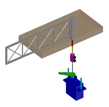
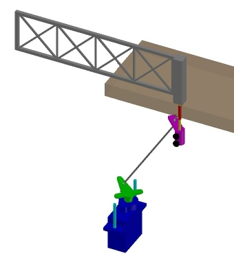
An anatomy
Here is my design to move the gates of a Level Crossing
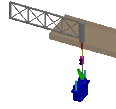
There are two designs, one for direct drive (I have called it Vertical) and the second is indirect (I have called it Horizontal) and is a little more low profile if space under the board is limited.
The Vertical design shown is for one servo per gate, but can be multiplied for two or four.
The horizontal design could be done with 2 or 4 servo's, but could equally be split into a tree of rods to drive all.
Instructions
Drill a hole up the gate post (grey)
Glue brass rod in (yellow)
Glue brass tube (red) into base board (brown), ensure it is at right angles in both directions
When set, drop the gate brass rod into tube with a plastic washer between to act as a bearing surface
Cut away plastic from one connector block to reveal the “two screw rod connector”
Attach to brass rod half way in, with one screw
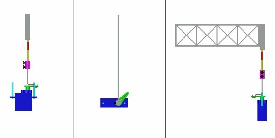
Bend piano wire (silver) to fit in servo lever (see pic below)
Attach servo to servo bracket
Assemble linkage (silver) to servo and offer up under board, mark mounting holes and affix bracket to board
Make final connection to “two screw rod connector” (purple) in the other side
Note 1
The servo bracket can be bought from MERG (v. 690 or h.681) or wooden (laser cut ply) {Ebay have a few offerings} or Peco, etc.
You can make your own from sheet brass/aluminium or wood
Or design your own and print in 3D
Note 2
Servo control can be bought from the likes of Peco, Megapoints, MERG, sometimes specific offerings from china on Ebay
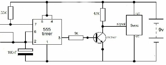
Or make your own with 555 timer or arduino or raspberry.
For the Horizontal “two screw rod connector”, a (similar size to servo lever) strip of brass is required, with holes drilled in a row, soldered to the brass boss
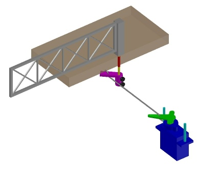
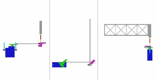
Here are the pic's of the design for the horizontal indirect drive type
Here are the pic's of the design for the vertical direct drive type
I have not actually built one yet, but it is loosely similar to other designs I have seen, that have been built, it's just they tend to be finished products that make it hard for the inexperienced to envisage how it's constructed. Hence I did the design in CAD, so that it is more understandable to all.
a. Any make of gate would work, most have a protruding bar that locates in a layout hole, the metal rod could be drilled up that or direct in the post if it were cut off.
b. I could tell you to use a Vee block and set with a spirit level, set on flat surface, with drill similarly positioned opposite, or put in a four jaw truck of a lathe and centre with DTI, or scan with 3D laser alignment tool and set point cloud data into CNC milling machine, but I won’t! Just do it by eye! :D
If the eye method gets it slightly out of true, it does not matter as the brass bar is easy to bend to bring it in line. Just make sure you start the hole in the centre, if it wanders off further in, a tweak with fingers or pliers will soon sort it out.
More importantly, it's imperative the (red) sleeve that it sits in, is at right angles (in two directions) to the surface of the layout. Best to glue the tube, with a plain rod in and support the rod with two square objects at right angles to each other) while it sets.
I am currently working on a magnetic coupling instead of the brass boss, so that accidental crashes will not harm the mechanism!
Having nearly completed a barrier type level crossing with flashing lights, I will soon write it up and add as a guide!
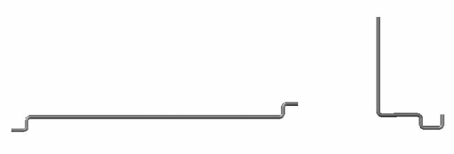
Design of wire for the horizontal indirect drive type
Design of wire for the vertical drive type
For those with a dilemma over driving the servo with home made/programmed (picaxe, rasberry, arduino, PC, etc.), there are several ready made circuits available like:-
http://www.blocksignalling.co.uk/index. ... riers-lcs5
https://www.heathcote-electronics.co.uk ... ssing.html
You could even build your own with a 555 timer circuit, but the easiest and cheapest for instant gratification, is to use a servo tester, most hobby shops have them or wait 6 weeks from china and much cheaper.
 Back to HOW TO